
Microfacet-based normal mapping is an alternative way of faking geometric details without corrupting Monte Carlo based path tracing light transport and it's available in ReflectMultiScatter and ReflectGeneralized. Theoretically it is well-defined, symmetric and fully energy conserving. On the other side it means that classic normal mapping has none of the properties above resulting in a tecnique that leaks energy and produces artifacts.

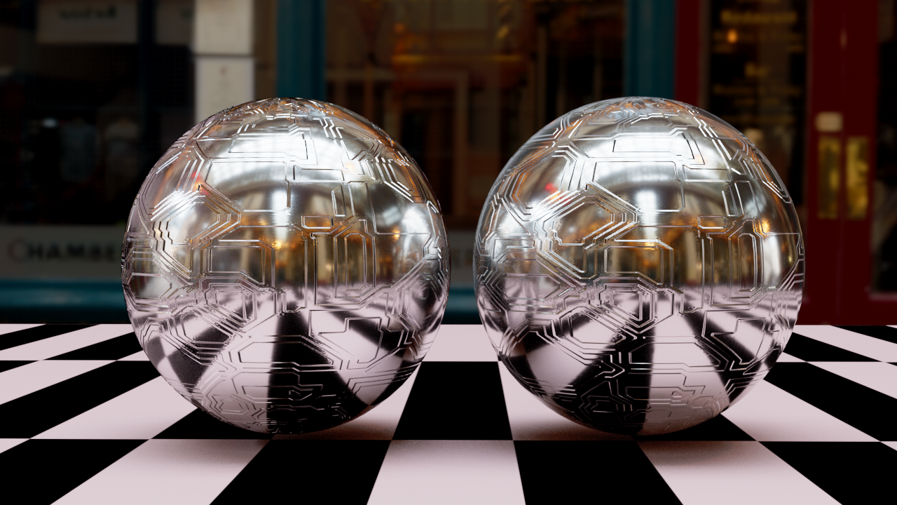
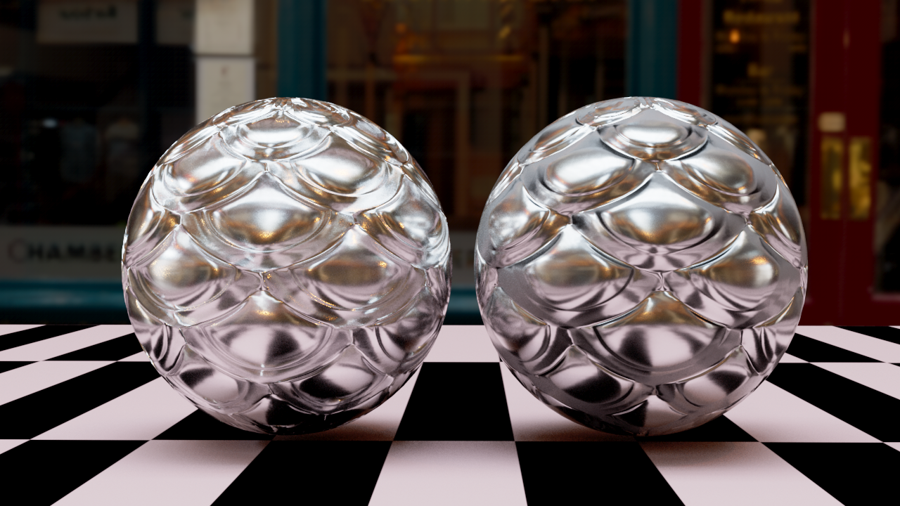
It looks that Arnold guys have recently done some work after our report on how much Standard Material was leaking energy because of the lack of multiple scattering reflections and the use of classic normal mapping. However we're still a tad better than Standard as we can see in the following images. If we look at the first image on the bottom left cube side (rendered with Standard Material) we shall already see some artifacts in the form of black fringes. Meaning, we have a front area light so why we have some pitch black stuff there and how we can check it is wrong stuff ?
There's an easy way to test these kind of things. It is called white furnace test. We apply a full white dome light to the scene (ie. add a dome light and keep its default settings). We cranck up all the reflection knobs (diffuse base and specular with full metalness) so to have a Fresnel of 1 everywhere. If the environment is fully white and we're fully reflecting it then our geo object should become completely white and disappear in the environment. But only if it is fully energy conserving and no other artifacts are there to let it leak energy.


It's easy to see that Standard mat isn't fully energy conserving where the bump is causing artifacts. If instead on the right of the Standard mat we can't see anything else than white pixels.. well that's Reflect Generalized doing its part.. no artifacts and no energy leak.
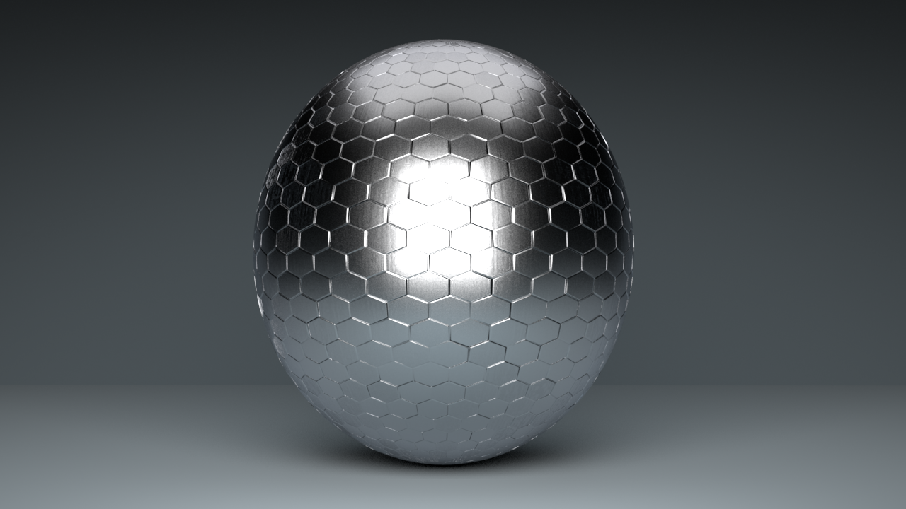
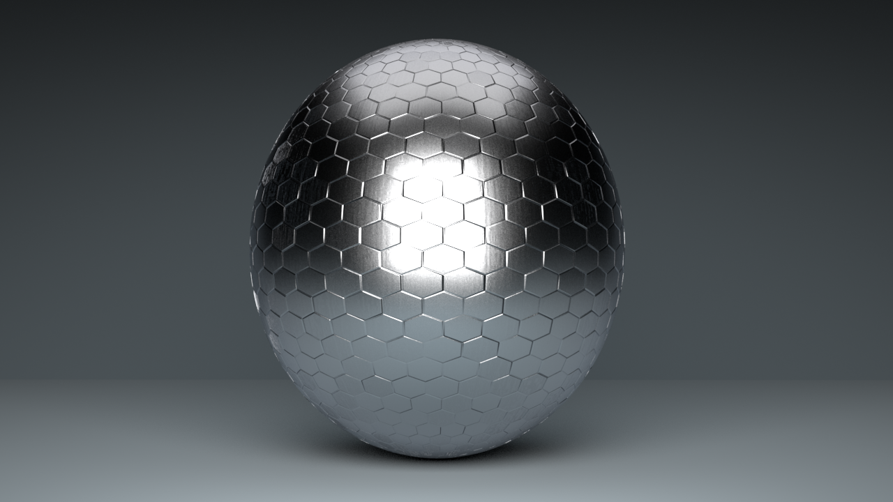
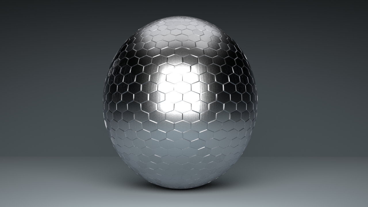
Here another test scene. This time normal mapping is a bit harder for both materials. However you have enough insights now to see by yourself what's the one that is performing better.

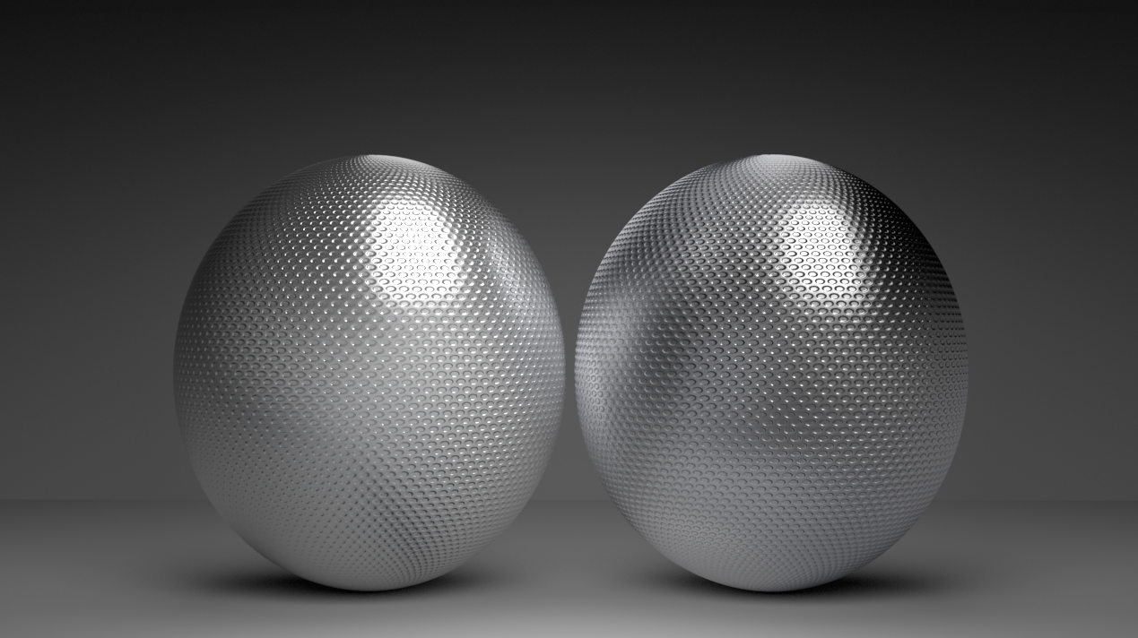
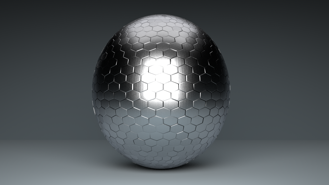
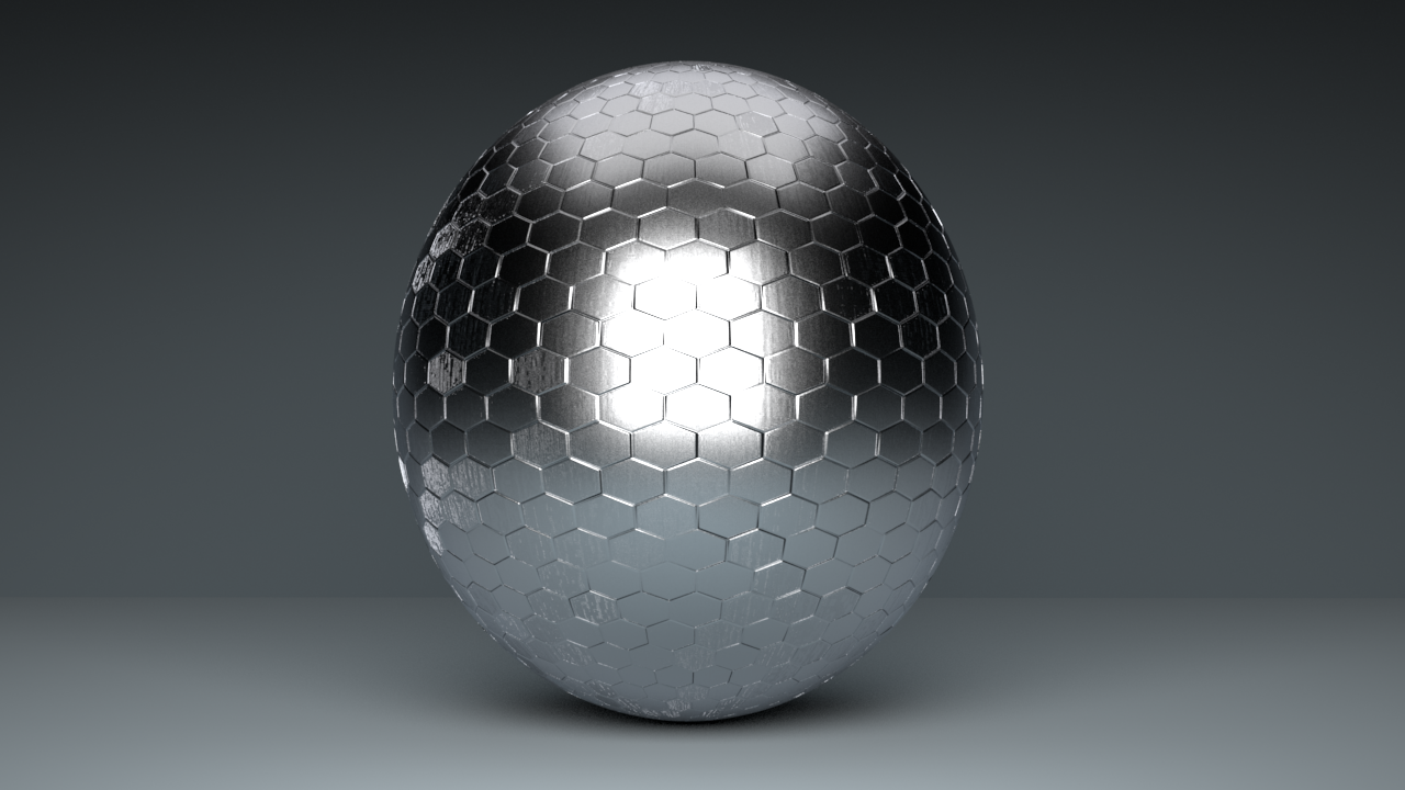
When we use bump/normal maps with fine details there're other issues we may find. Standard mat is loosing detail at grazing angles and also the overall material appearance is getting a bit weird, we can no more tell if it is metal or plastic because of the lack of highlights where details get finer. In the second image instead we have both lack of details and black fringes. Rombo Reflect (right) instead remain crips and with a well defined metallic appearance.

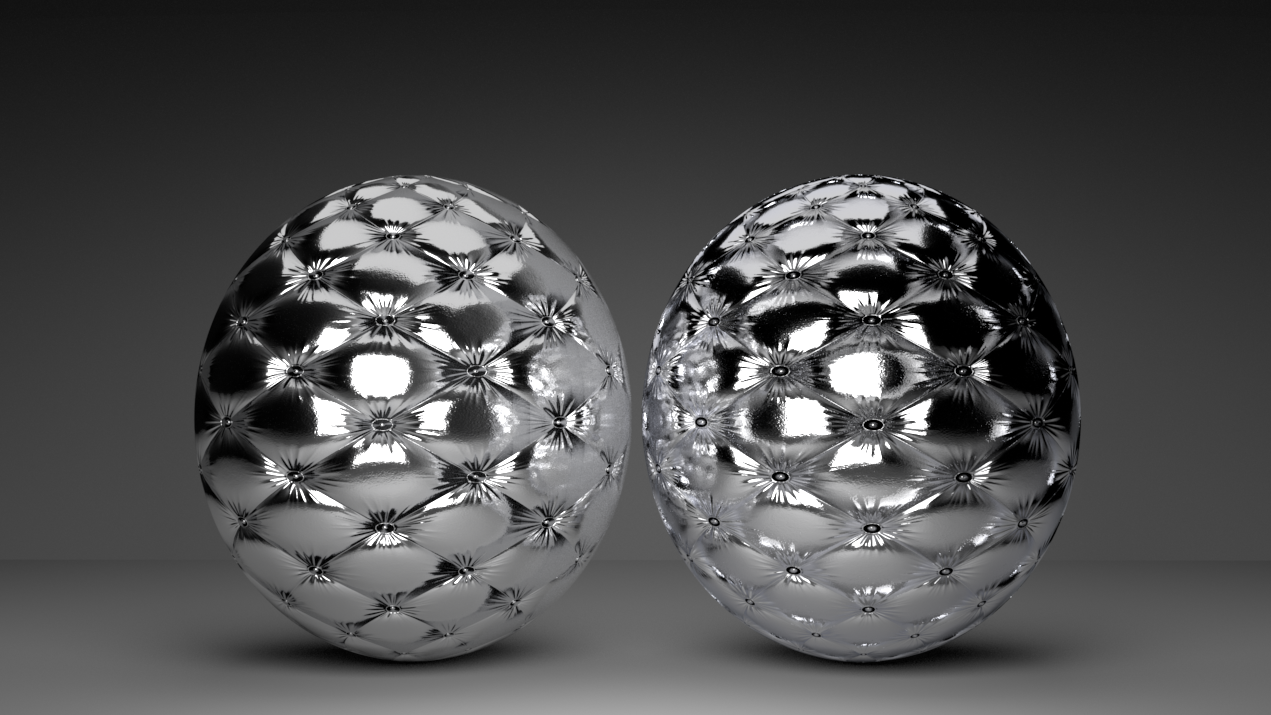
Below it is way more evident how consistent is rombotools normal mapping compared to Arnold standard surface. What's that grey patina on both balls on the right (aistandardsurface) ? We don't wanna know :) (probably some lambertian brdf injection for normals that go brrrr, not a solution).
Let's see what are the main parameters
that make up our microfacet-based normal mapping approach.

First of all, the microfacet stuff is only for reflections.. which also means that if we want different maps for diffuse and specular lobes respectively..
-> we'll plug one in the usual geometry bump slot and
-> the other one in the micro-facet normal slot.
Even there the Bump Mode is only for reflections, the diffuse part is using automatically a modified classic bump mapping like in the Standard mat.
Second, there're two ways to use microfacet-based normal mapping :
- the analytical approach which is an approximation,
- the other one which is the full random walk thing.
The former is faster and automatic (without parameters) but less precise than the latter.
Third, microfacet-based normal mapping is better used with high roughness values (>0.2) as with low roughness values it is still a bit unstable and could return fireflies.
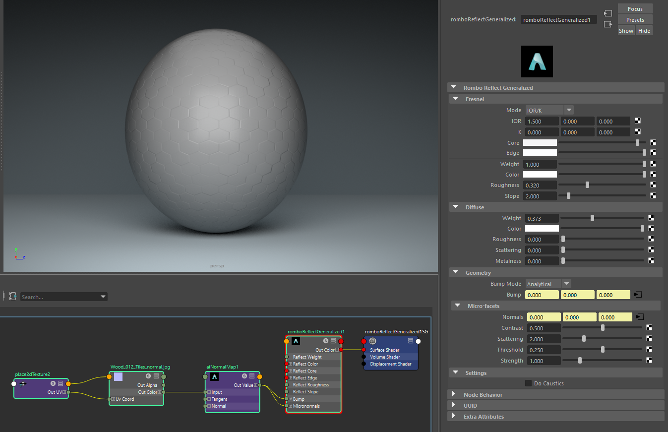
The overall setup is to simply plug a normalmap node (ainormalmap) into the micronormals slot.


Generally, the default param values are already good for most of the cases.
Let's see however specifically what each of them really does.
With the Contrast param we have fine control on how visually our highlights will appear on the bumped geometry. For a physically based appearance set it to 0.5
With the Scattering param we control how many bounces we're doing while random walking the microfacet profile. Less bounces (min is 1) means darker stuff while more bounces will bring more light in. Keep in mind that the more bounces the longer the time to render. Together with the above Contrast param we can try to keep more highlights there while here we may reduce Scattering to get faster render times.
The Threshold param is here to avoid some kind of artifacts when our bump/normal maps have too fine details. Situation is that they are not really artifacts but real bump details however the problem is that classic normal maps would not go that deep into details and so the maps we already have may need to be tweaked because they were not done esplicitely for microfacet-based normal mapping; with the Threshold param we tweak them here. Below 0 and 0.5, default is 0.1. We can also deal a bit with Scattering and Contrast params if our normal maps return too much unpleasant detail.. generally just reduce a bit Scattering and increase Contrast.

The Strength param controls how much we'll displace our normals and it's the same as tweaking bump height or normal strength on the respective bump/normal node params. It is mainly here because if we want the same pattern to appear also as diffuse bump we need to plug the same aibump/ainormal into the bump geo slot.. so here we can control a different amount of bump just for reflections. Keep in mind this setup is usefull only for when we want to go for microfacet-based stuff.. without we would just plug it as usual in the bump slot and both diffuse and reflection would have the same bump effect.
In the situation instead where we want a certain bump for the diffuse lobe while a different one just for the specular lobe the setup is still super simple.. we just plug the diffuse bump into the bump slot and the reflection bump into the micronormals slot. Below the tiled bump is from the diffuse part while the coating has just a noise bump on top. Because we don't generally need micro-bump for dieletric stuff keep the Scattering param the lower possible for faster render times.

All in all we have a bunch of easy extra params to extensively tweak our bumped appearance while helping our belowed pathtracer to stay true and more physically correct. Bump and normal mapping as have been done for decades introduced so much artifacts that they are now a kind of estetics so that when dealing witht the correct thing we may even find it a bit un-estetical because of that; we have illustrated our main params to finely tweak the overall appearance and finely balance it over the previous look or toward a more correct one.
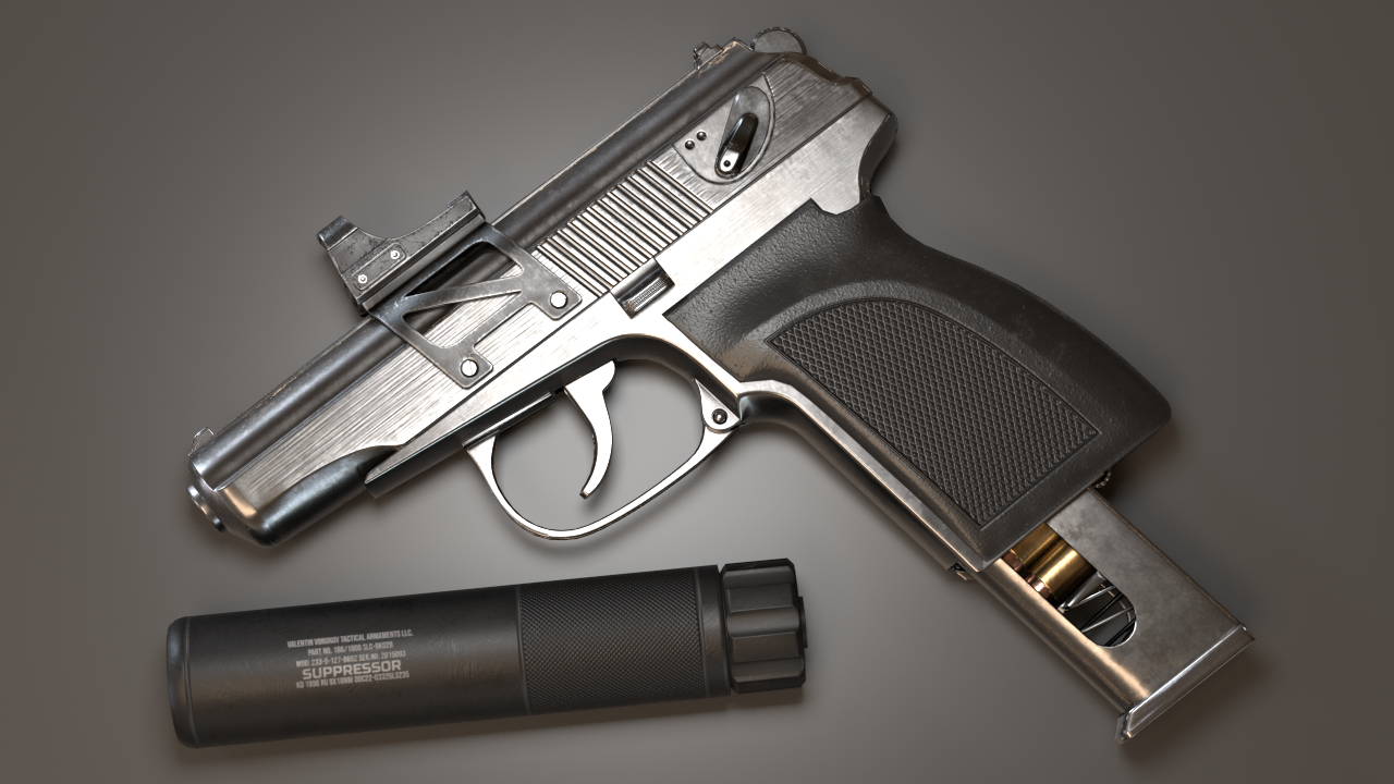
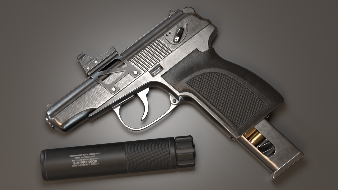
Here we can see how much more detail we bring in with microfacet-based normal mapping. It's already nice with just plain normal mapping but with analytical bump mapping we have less flat zones and more vibrant shading because it's not only how bump will actually display but how the whole model will do because classic bump mapping tends to just flat out incoming light.. look for example at the suppressor/silencer highlights or at the bullets loader bottom right highlights.
Eventually a quarter dollar with a displacement quality bump.. no geometry has been actually displaced.

Keywords :
arnold, arnoldrender, arnoldrenderer, shader, material, reflect, reflection, microfacet, arnold shaders, arnold download, arnold materials, arnold renderer materials